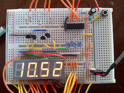
This I realised would make a good clock project.
With the PIC16F505 there are 14 pins, one for VCC on for GND and 12 can be used for I/O, 4 for controlling each 7 segment display, 7 for the individual segments and 1 to act as a time adjustment input. One of the pins can only be an input but all the others are bi-directional if needed so the input only pin was assign for the clock adjustment.
Something to bare in mind when writing code for a clock is that you must keep refreshing the display. Its no good writing the time out then waiting for a minute because all you will see is the last digit. You have to keep writing over and over to fool the eye into seeing a continuous display. In order to do this you must sync the time between displaying each digit. The internal clock runs at 4MHz and the internal timer (TMR0) is incremented on each instruction cycle which is made of 4 clock pulses. Effectively then the timer is 1/4 of the clock i.e 1MHz. By setting the PIC prescaler to 1:32 (dividing the timer by 32), you have time to run code to display one digit and wait for 125 tics at 1MHz/32/125 which makes 4ms. So the time between displaying each digit is 4ms. Keeping a count of the 4ms increments, when we reach 250 we have 1 second. Keep a count of the seconds and you then have your minutes.
The prescaler effectively tells you how many instructions can be executed between TMR0 tics so at 1:32 it equates to 32 instructions. The whole of my PIC program is 163 instructions (163 12bit bytes). We wait for 125 lots of 32 instructions before we increment the 4ms counter and move onto the next digit. What I am trying to point out here is that TMR0 may have ticked over a few times before you reach the checking loop.
One last timing issue is how to check for the clock-set button being pressed. This also needs to be done between each digit and allow the minutes to incremented reasonable quickly to set the time. This can be done by checking bit 5 of the 4ms counter, if set then check the input line and if that's set then increment the minutes.
Here some of the timing code that sits between each digit being displayed to show you how I've done it:
; time synchronisation
wait      movf   TMR0,W    ; get timer  4MHz/4cy/32 = 32us
          xorlw  .125      ; compare with 125 x 32us = 4ms
          btfss  STATUS,Z  ; if not equal
          goto   wait      ; then continue waiting

; If TMR0 register is written, the increment is inhibited for the
; following two cycles. The user can work around this by writing
; an adjusted value to the TMR0 register.

; increment 4ms counter
          movlw  8         ; advance 8x32us to allow for TMR0 reset
          movwf  TMR0      ; reset TMR0 with adjusted value
          incf   CNT1      ; increment 4ms timer

; check for clock set
clkset    btfss  CNT1,5    ; check every time bit 5 goes hi
          goto   incsec    ; if not set goto incsec
          movf   PORTB,W   ; Get input from PORTB
          andlw  b'001000' ; Line high?
          btfss  STATUS,Z  ; If not -- active low
          goto   incsec    ; got incsec
          incf   MINUTE    ; increment minute
          clrf   SECOND    ; reset seconds to zero
          clrf   CNT1      ; clear 4ms counter
          goto   lomin     ; go check the minutes

; increment seconds
incsec    movf   CNT1,W    ; get 4ms counter
          xorlw  .250      ; compare with 250
          btfss  STATUS,Z  ; if not equal
          goto   check     ; goto check
          incf   SECOND    ; else increment second
          clrf   CNT1      ; reset 8ms timer

; check time
check     movf   SECOND,W  ; get seconds.
          xorlw  .60       ; compare with 60.
          btfss  STATUS,Z  ; if not
          goto   lomin     ; goto lomin,
          incf   MINUTE    ; else increment minutes.
          clrf   SECOND    ; clear seconds.

;work out new time
lomin
The breadboard layout looks like this:

