
Tuesday 7 August 2012
37. Raspberry Pi Case.
Just got this case for my Raspberry Pi. I got it from http://www.modmypi.com. Its very good. Fit is perfect, it doesn't rattle around in the case and the quality is very good too. You can choose any colours you like and even mix and match top and bottom case colours. The case clips together very solidly and comes with some stick on clear rubber feet. Well worth the money.

Friday 3 August 2012
36. Apple 1 - Hello World!
It's been a while. I've been getting distracted by all things geeky. I thought I'd share this though.
I became curious by the Apple-1, the original must have Apple product, the Ford Model T of computers if you like. All you got was a circuit board, but no keyboard or monitor (a bit like the raspberry Pi of its day). I decided to look for an emulator for it, and at this stage knew nothing of the Apple-1's underpinnings. It wasn't a Z80 but my old friend the 6502. I've not touched the 6502 since secondary school when I used to play with the Commodore PET/CBM in the early 80's.
I got the Pom-1 emulator in Java flavor and downloaded the Apple-1 manual.
I soon realised that to program the Apple-1 you just entered 6502 machine codes and ran the machine code programs. No BASIC interpreter (although there is a 6502 program for the Apple-1 that you can load in to get BASIC). So I set about relearning 6502 machine language and so far my efforts have resulted in my first "Hello World!" program.
Here's a screenshot of the code and it running:

\ is the only screen indication that the Apple-1 is alive. 0.22 displays the first 23 bytes and R runs from address 0.
Why is this relevant? Well this is something like what I want to build with the Z80
I became curious by the Apple-1, the original must have Apple product, the Ford Model T of computers if you like. All you got was a circuit board, but no keyboard or monitor (a bit like the raspberry Pi of its day). I decided to look for an emulator for it, and at this stage knew nothing of the Apple-1's underpinnings. It wasn't a Z80 but my old friend the 6502. I've not touched the 6502 since secondary school when I used to play with the Commodore PET/CBM in the early 80's.
I got the Pom-1 emulator in Java flavor and downloaded the Apple-1 manual.
I soon realised that to program the Apple-1 you just entered 6502 machine codes and ran the machine code programs. No BASIC interpreter (although there is a 6502 program for the Apple-1 that you can load in to get BASIC). So I set about relearning 6502 machine language and so far my efforts have resulted in my first "Hello World!" program.
Here's a screenshot of the code and it running:
\ is the only screen indication that the Apple-1 is alive. 0.22 displays the first 23 bytes and R runs from address 0.
Why is this relevant? Well this is something like what I want to build with the Z80
Sunday 20 May 2012
35. Floppy Drive Music. Stage 1.
Ok well, I need to find time to understand the radio stuff, so I'm gonna park that for now and move on to Floopy Drive Music. Ok yes, its been done before (as has most of the stuff I'm doing), but I haven't done it yet.
So what is floppy drive music? Well by stepping the drive's motor at different speeds we can get different pitches from it. Combine the different pitches and you get music.
I'm going to use the Arduino Uno to start with but I may program a PIC chip to do the same later.
After a bit of reading on the web, it seems the Arduino will not have enough power from the +5V supply to power the floppy drive. Its recommended to use another power source.
So I have an old PC power supply handy which should do the job. However, when its disconnected from its host PC's motherboard, its does nothing when plugged into the mains. Fortunately you can fake this by shorting the PS_ON# pin to it's adjacent COM (see http://www.smpspowersupply.com/connectors-pinouts.html for pin details).
Of course using a PC PSU (Power Supply Unit) means it come with all the connectors to connect to the power pins of floppy drive, and andthing else you might want to plug in.
Pins connected, plugged in and powered on. Fan on the PSU starts and floppy drive makes a short whirring noise.
Thursday 12 April 2012
34. Diversion into radio.
The lack of any joy with the MSF signal has got me thinking about radio electronics.
I connect a wire to CH1 on my Xprotolabs Oscilloscope because I remember getting random signals once before.
Here's watch I picked up.
 Its very weak, the oscilloscope settings are at max resolution. Somewhere in there is probably the MSF signal.
Now while this is a divergence from the Z80 theme, I think its well worth looking into so improve my electronics knowledge as this is part if the journey.
So I learnt recently about transistors, and how they can amplify a signal. So lets amplify this and see what we can make of it...
Here's watch I picked up.

Now while this is a divergence from the Z80 theme, I think its well worth looking into so improve my electronics knowledge as this is part if the journey.
So I learnt recently about transistors, and how they can amplify a signal. So lets amplify this and see what we can make of it...
Thursday 5 April 2012
33. Radio Ga Ga
Rather than set the time myself, I thought I might be able to get the time signal from the Rugby Transmitter in the UK. Well its not in Rugby anymore but the name still sticks. Its in Anthorn in Cumbria and is called the MSF Signal transmitting on 60KHz. The National Physics Laboratory (NPL) give you all the details of how to decode the signal so all I need is a receiver.
I bought one from PV Electronics. It come with an antenna and a receiver module which sends a signal that you can simply connect to an IC and decode the message.
Well I get a signal, but not very well. Its anything I can use. I should get a pulse of varying length every second, but all I get are random on/offs. I have no way to tell if either the antenna or the receiver are faulty. I am assuming that I am not getting very good reception. It does get better when I point the antenna directly towards Anthorn, but still nothing useful.
Maybe I just need a bigger antenna, so I started reading about them so I could make one, and found that its not a simple subject. Check this out: http://www.antenna-theory.com/ My brain hurts!
A glimmer of hope though, it turns out that MSF was turned off from 26/03/2012 until today. Alas no, still a random signal.
Saturday 3 March 2012
32. PIC Clock - Tic 2
I wanted to see how far I could push the clock idea by adding two more dual 7 segment displays to add seconds and information. This meant controlling 8 transistors, however with all pins on the PIC16F505 used up from the last version I had to come up with a way to control 8 digits from 4 pins. Well as it happens, using binary, 3 pins are enough to control 8 outputs. Binary 000 to 111 is 8 different values.
Now as luck would have it, there is such a thing as an 8 bit decoder controlled by 3 inputs in the guise of a 74LS238. There are many manufacturers and I used an M74HC238B1 from ST Microelectronics. Its does exactly the same thing.
Using 1 less pin to control the 8 digits means I have a pin left over. This gives me an extra button to control the functions of the clock. I have yet to program these in but the its all wired up ready. All you can do is increase the minutes as before. The day was hardcoded so it always says SA for Saturday.
I programmed in the entire alphabet (well as best you can with a 7 segment display as M,W,K,Q and X are not ideal) and this means I can display the day (Mo, Tu, We etc.), mode (AL for alarm, Yr for year etc.) amongst other uses I have yet to conjour.
Here is it displaying Saturday 10:39 and 41 seconds.

With the additional displays there is a noticeable flicker as each one is updated and this is because the delay between refreshing each digit has doubled from 4x4ms to 8x4ms. I've not addressed this as its not that bad. Using a faster external oscillator is one option but all pins on the PIC are used so the alternatives are to halve the prescaler for TMR0 or use a different PIC with a faster internal oscillator.
Saturday 18 February 2012
31. PIC Controlled Digital Clock.
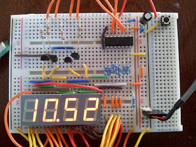
Following on from my new found friend the transistor, I had the idea to use four of them to switch on four 7 segment LED displays. Using 7 outputs from the PIC16F505 to control the segments a,b,c,d,e,f & g, another 4 outputs would switch each digit on in sequence. As it would be very fast you would see all digits on.
This I realised would make a good clock project.
With the PIC16F505 there are 14 pins, one for VCC on for GND and 12 can be used for I/O, 4 for controlling each 7 segment display, 7 for the individual segments and 1 to act as a time adjustment input. One of the pins can only be an input but all the others are bi-directional if needed so the input only pin was assign for the clock adjustment.
Something to bare in mind when writing code for a clock is that you must keep refreshing the display. Its no good writing the time out then waiting for a minute because all you will see is the last digit. You have to keep writing over and over to fool the eye into seeing a continuous display. In order to do this you must sync the time between displaying each digit. The internal clock runs at 4MHz and the internal timer (TMR0) is incremented on each instruction cycle which is made of 4 clock pulses. Effectively then the timer is 1/4 of the clock i.e 1MHz. By setting the PIC prescaler to 1:32 (dividing the timer by 32), you have time to run code to display one digit and wait for 125 tics at 1MHz/32/125 which makes 4ms. So the time between displaying each digit is 4ms. Keeping a count of the 4ms increments, when we reach 250 we have 1 second. Keep a count of the seconds and you then have your minutes.
The prescaler effectively tells you how many instructions can be executed between TMR0 tics so at 1:32 it equates to 32 instructions. The whole of my PIC program is 163 instructions (163 12bit bytes). We wait for 125 lots of 32 instructions before we increment the 4ms counter and move onto the next digit. What I am trying to point out here is that TMR0 may have ticked over a few times before you reach the checking loop.
One last timing issue is how to check for the clock-set button being pressed. This also needs to be done between each digit and allow the minutes to incremented reasonable quickly to set the time. This can be done by checking bit 5 of the 4ms counter, if set then check the input line and if that's set then increment the minutes.
Here some of the timing code that sits between each digit being displayed to show you how I've done it:
The breadboard layout looks like this:
This I realised would make a good clock project.
With the PIC16F505 there are 14 pins, one for VCC on for GND and 12 can be used for I/O, 4 for controlling each 7 segment display, 7 for the individual segments and 1 to act as a time adjustment input. One of the pins can only be an input but all the others are bi-directional if needed so the input only pin was assign for the clock adjustment.
Something to bare in mind when writing code for a clock is that you must keep refreshing the display. Its no good writing the time out then waiting for a minute because all you will see is the last digit. You have to keep writing over and over to fool the eye into seeing a continuous display. In order to do this you must sync the time between displaying each digit. The internal clock runs at 4MHz and the internal timer (TMR0) is incremented on each instruction cycle which is made of 4 clock pulses. Effectively then the timer is 1/4 of the clock i.e 1MHz. By setting the PIC prescaler to 1:32 (dividing the timer by 32), you have time to run code to display one digit and wait for 125 tics at 1MHz/32/125 which makes 4ms. So the time between displaying each digit is 4ms. Keeping a count of the 4ms increments, when we reach 250 we have 1 second. Keep a count of the seconds and you then have your minutes.
The prescaler effectively tells you how many instructions can be executed between TMR0 tics so at 1:32 it equates to 32 instructions. The whole of my PIC program is 163 instructions (163 12bit bytes). We wait for 125 lots of 32 instructions before we increment the 4ms counter and move onto the next digit. What I am trying to point out here is that TMR0 may have ticked over a few times before you reach the checking loop.
One last timing issue is how to check for the clock-set button being pressed. This also needs to be done between each digit and allow the minutes to incremented reasonable quickly to set the time. This can be done by checking bit 5 of the 4ms counter, if set then check the input line and if that's set then increment the minutes.
Here some of the timing code that sits between each digit being displayed to show you how I've done it:
; time synchronisation
wait      movf   TMR0,W    ; get timer  4MHz/4cy/32 = 32us
          xorlw  .125      ; compare with 125 x 32us = 4ms
          btfss  STATUS,Z  ; if not equal
          goto   wait      ; then continue waiting

; If TMR0 register is written, the increment is inhibited for the
; following two cycles. The user can work around this by writing
; an adjusted value to the TMR0 register.

; increment 4ms counter
          movlw  8         ; advance 8x32us to allow for TMR0 reset
          movwf  TMR0      ; reset TMR0 with adjusted value
          incf   CNT1      ; increment 4ms timer

; check for clock set
clkset    btfss  CNT1,5    ; check every time bit 5 goes hi
          goto   incsec    ; if not set goto incsec
          movf   PORTB,W   ; Get input from PORTB
          andlw  b'001000' ; Line high?
          btfss  STATUS,Z  ; If not -- active low
          goto   incsec    ; got incsec
          incf   MINUTE    ; increment minute
          clrf   SECOND    ; reset seconds to zero
          clrf   CNT1      ; clear 4ms counter
          goto   lomin     ; go check the minutes

; increment seconds
incsec    movf   CNT1,W    ; get 4ms counter
          xorlw  .250      ; compare with 250
          btfss  STATUS,Z  ; if not equal
          goto   check     ; goto check
          incf   SECOND    ; else increment second
          clrf   CNT1      ; reset 8ms timer

; check time
check     movf   SECOND,W  ; get seconds.
          xorlw  .60       ; compare with 60.
          btfss  STATUS,Z  ; if not
          goto   lomin     ; goto lomin,
          incf   MINUTE    ; else increment minutes.
          clrf   SECOND    ; clear seconds.

;work out new time
lomin
The breadboard layout looks like this:

Saturday 11 February 2012
30. Christmas Lights with Transistors
A component I haven't used yet: The Transistor.
I had some battery operated Christmas lights. They were static, always on, with red, green, orange and blue LEDs.
I wondered if I could make them flash. As it turns out they were wired into two groups, red/orange and green/blue. At one end they were connect all together at the positive terminal and at the other end they two groups each connected to a resistor and the negative terminal. As this was all wound up in plastic sheath I would probably have damaged it trying to separate all the wires, so I left it as it was and went with the two grouped colours.
Now as the red/orange and green/blue were connect to the negative terminal via a resistor each, this meant they were outputs, that is +5---LED---Resistor---GND.
In order to program a PIC chip to control them I needed an input. This was not going to work, so I figured I could use an NPN Transistor to act as a switch.
I programmed a PIC12F508 to connect to pins to two transistors to switch the LEDs on and off. I also incorporated a 4-gang DIP switch to allow 16 flashing modes. I ended up just having Switch 1 as a fast/slow option, switches 2 & 3 to give 4 flashing modes and switch 4 enables the original static always on mode.
Here's my breadboard layout before I soldered it all together and put it into battery compartment and put a USB cable to provide +5V power instead of 4.5V with batteries.

Subscribe to:
Posts (Atom)